Liabe Brave
Member
There's a lot of confusion about the new technique of checkerboard rendering (CBR). The most pervasive is that it's a form of upscaling, taking a set of rendered pixels and doubling them to create the final image. While this idea is inspired by a step in the real process, it's a misunderstanding and doesn't capture the entire method. This leads to bad estimates of the costs, benefits, and possible applications of CBR.
I'll try to describe what CBR actually does, and compare it to standard rendering and upscaling. The difficulty with this plan is that I have no training as a computer scientist! My knowledge derives completely from reading on the web, and from discussion on GAF. Therefore, please take the following explanation with a huge grain of salt. I know there are very knowledgeable folks here, so I'd be happy to make revisions wherever I've made mistakes. I expect that there are mistakes.
The typical basis of computer graphics for games is polygonal models or meshes. These describe the objects in a scene, with smooth curves approximated by flat shapes joined together. As a base example we'll work with throughout, imagine a piece of debris being tossed by an explosion. Two frames in sequence might show something like this:
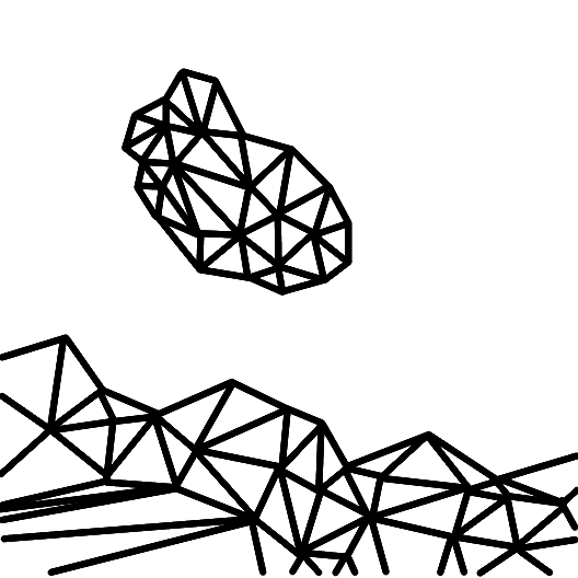
Time is advancing from left to right
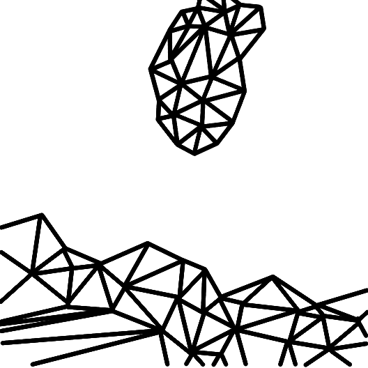
These models are mathematical, giving them immense precision. But the screens they're displayed on have a limited number of pixels. Details in the polygonal scene will thus not exactly match this grid. Some pixels may contain only a sliver of a polygon; others will overlap multiple polygons. Since each pixel can only be one solid block of color, the renderer must decide what the best value is. This process of turning a 3D scene into a 2D grid of pixels is called rasterization.
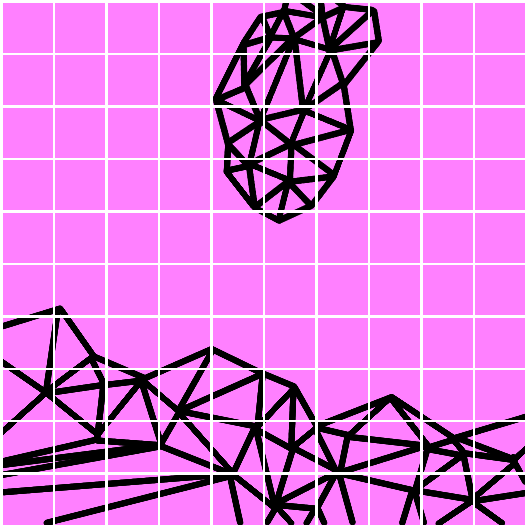
The details inside each pixel can't be displayed
At the most basic level, each pixel's value is determined by checking which polygon covers the center of the pixel. Polys closer to the camera take precedence. Here's three scenarios, showing the polygon positions in the top row, and the final pixel value below them.
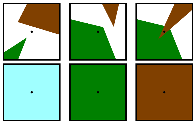
In the first case, no polygon covers the center, so the pixel is "see through", and the final value comes from the skybox behind everything. In the second case, the pixel is set to green. Note that there is no blending of pixel color--not even a hint of brown in the green. In the third case, both polys cover the center but the pixel is set to the color of the nearest one. Note that the fact that the green polygon covers more of the area is ignored.
Repeated for all pixels, the result for our example might end up looking something like this:
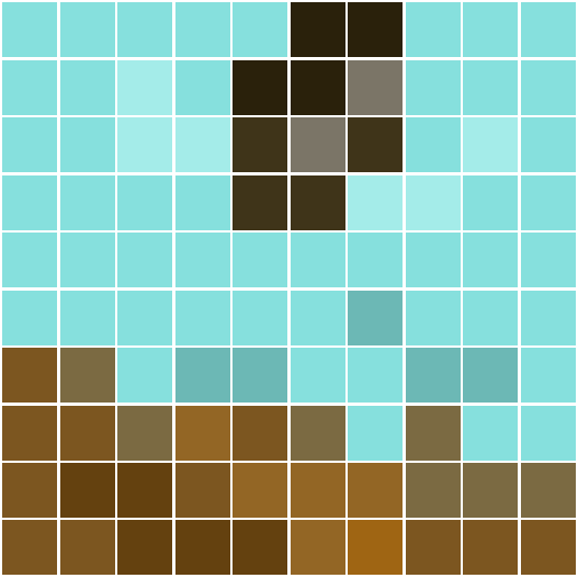
This is a start, but there are more influences to a scene's appearance than the raw color of the objects in it. Therefore, rasterization continues with many more iterative steps of different kinds. It's an extremely complex process, and I couldn't fit all the details even if I knew them. But here's a vastly simplified diagram of some stages. Each one often includes multiple substeps.
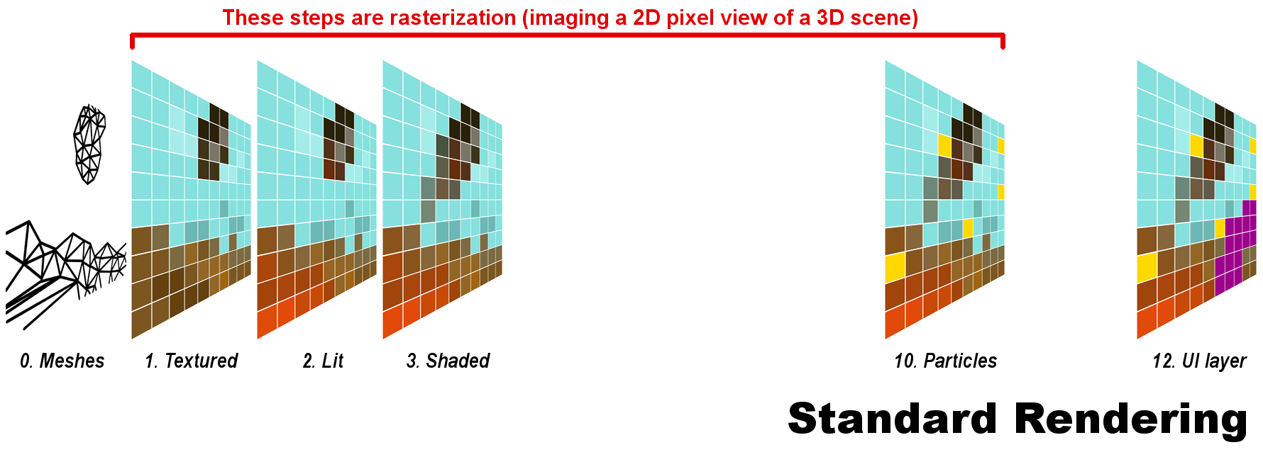
The reason for skipped stage numbers will become apparent.
1. Textured. Artists create flat drawings of detail that are wrapped around the models. This stage gives the same result shown before.
Our example shows the debris above some rocks, in front of a blue skybox.
2. Lit. Multiple sources of light may shadow or color the scene, adjusting pixel values again.
Our example has orange light from the offscreen explosion, also casting a glow on the debris.
3. Shaded. "Shaders" is a catchall term for methods that adjust the results from previous stages. They can do a great many different things, increasing realism or stylizing the image.
Our example adds motion blur to the flying debris.
10. Particles. Very small elements may skip the computationally expensive prior stages, and be added at the end.
Our example has flying sparks from the explosion.
12. UI layer. The user interface is almost always added last, as a 2D overlay on the image.
Our example shows the corner of a waypoint marker.
The calculations needed to determine every final pixel value are complex and time-consuming. CBR was invented as a way to cut some of the cost, without reducing the number of pixels in the final image.
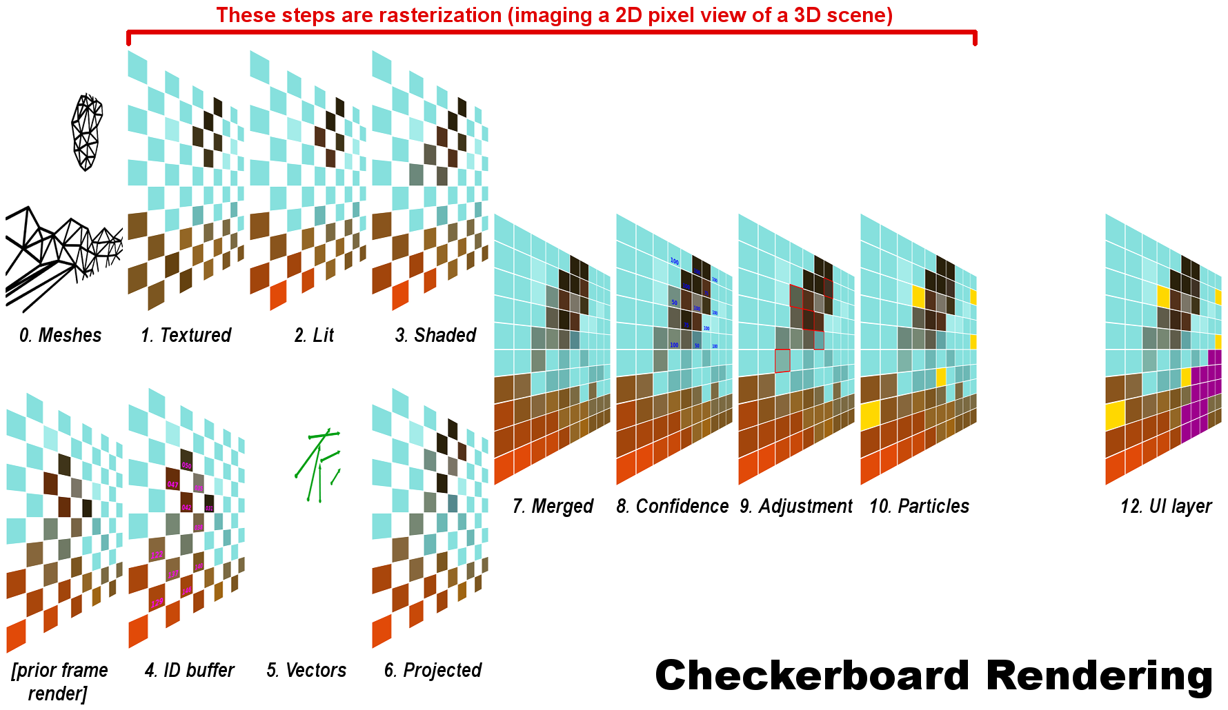
Each frame begins with two separate rendering paths. (Very often CBR is conceived as having these occur sequentially, but I don't know of any technical reason they can't be done in parallel up to a point.)
Stages 1 to 3 are identical to standard rendering, but done only for every other pixel. In each successive frame, which pixels are rendered is switched back and forth. The result of this path is sent to Stage 7, and also forms the basis for the second path during the next frame.
4. ID buffer. Each object or polygon in the prior frame has a unique identifier (only some are shown).
5. Vectors. The ID of the polygon(s) associated with each pixel is tracked as it moves, creating a vector. Everything that moves is tracked, but I've shown only a few vectors to make things less cluttered. (Motion may also be tracked back two frames instead of one.)
6. Projected. The renderer uses the tracked origin and motion to move the old pixels into new positions.
7. Merged. The results from each path, which are opposite sets of pixels, are combined to make a whole frame. Note that the same number of pixels has been rasterized as in standard rendering.
8. Confidence. All the pixels from the second path have a confidence level, indicating likelihood of error due to erratic or extreme motion. (Only some confidence levels are shown.)
9. Adjusted. Pixels with low confidence levels are compared to their immediate neighbors, and their values adjusted by compromise with those adjacent pixels. This is the only step of CBR that uses a method like upscaling. Only some pixels are affected, and fewer as motion gets more predictable or takes up less of the screen. At 100% confidence, CBR becomes literally identical to standard rendering.
Our example outlines pixels that were adjusted due to low confidence.
Stages 10 and 12 are the same as with standard rendering.
CBR is one way of making rendering cheaper, but it's very complex and was only developed within the past few years. Previously, a common way to reduce render cost without reducing scene complexity was simply to render fewer pixels. Of course, the smaller frame then has to be blown back up to the correct size for the display. This is upscaling.
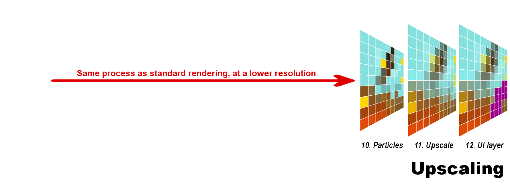
Stages 1 to 3, and Stage 10 all take place exactly as with standard rendering, simply at a lower resolution.
Our example assumes a 9:10 ratio, similar to a 900p:1080p upscale, or a 1800p:2160p one.
11. Upscaling. The frame is enlarged, so each original pixel now sits over portions of multiple pixels. A compromise method blends them and selects final values.
Our example shows the precise results, not an approximation or "what if" scenario. The method used is bilinear, which is due to extremely low computing cost on modern hardware.
Stage 12 is the same as with the other methods.
Here are the final frames of each method side-by-side.
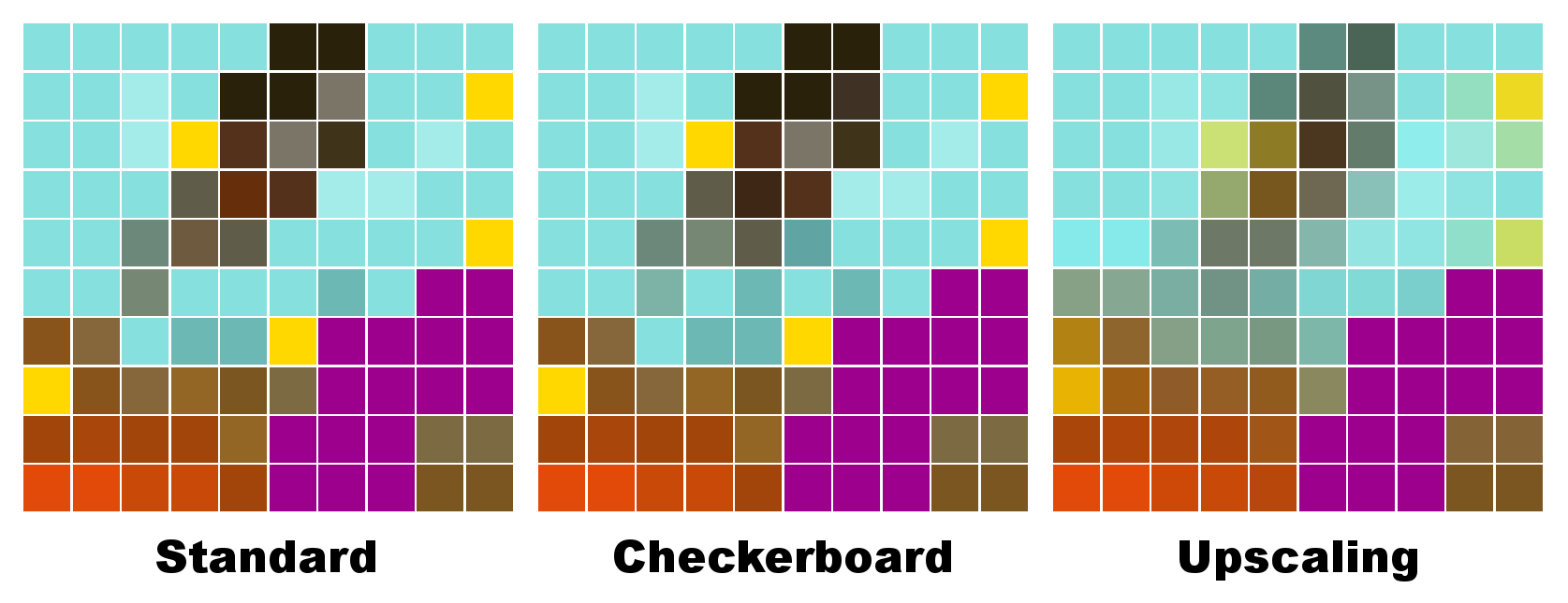
As you can see, both checkerboard and upscaling deviate from the "real" results of standard rendering. But despite the fact that they cost about the same in rendering time, it's clear checkerboarding gives much more accurate results. This may be more obvious in an animated comparison.
Hopefully this helps people understand what CBR does. I'll do my best to answer questions, and make alterations to fix my errors and improve clarity.
Thanks for sticking with this very long and complex post!
I'll try to describe what CBR actually does, and compare it to standard rendering and upscaling. The difficulty with this plan is that I have no training as a computer scientist! My knowledge derives completely from reading on the web, and from discussion on GAF. Therefore, please take the following explanation with a huge grain of salt. I know there are very knowledgeable folks here, so I'd be happy to make revisions wherever I've made mistakes. I expect that there are mistakes.
The typical basis of computer graphics for games is polygonal models or meshes. These describe the objects in a scene, with smooth curves approximated by flat shapes joined together. As a base example we'll work with throughout, imagine a piece of debris being tossed by an explosion. Two frames in sequence might show something like this:
Time is advancing from left to right
These models are mathematical, giving them immense precision. But the screens they're displayed on have a limited number of pixels. Details in the polygonal scene will thus not exactly match this grid. Some pixels may contain only a sliver of a polygon; others will overlap multiple polygons. Since each pixel can only be one solid block of color, the renderer must decide what the best value is. This process of turning a 3D scene into a 2D grid of pixels is called rasterization.
The details inside each pixel can't be displayed
At the most basic level, each pixel's value is determined by checking which polygon covers the center of the pixel. Polys closer to the camera take precedence. Here's three scenarios, showing the polygon positions in the top row, and the final pixel value below them.
In the first case, no polygon covers the center, so the pixel is "see through", and the final value comes from the skybox behind everything. In the second case, the pixel is set to green. Note that there is no blending of pixel color--not even a hint of brown in the green. In the third case, both polys cover the center but the pixel is set to the color of the nearest one. Note that the fact that the green polygon covers more of the area is ignored.
Repeated for all pixels, the result for our example might end up looking something like this:
This is a start, but there are more influences to a scene's appearance than the raw color of the objects in it. Therefore, rasterization continues with many more iterative steps of different kinds. It's an extremely complex process, and I couldn't fit all the details even if I knew them. But here's a vastly simplified diagram of some stages. Each one often includes multiple substeps.
The reason for skipped stage numbers will become apparent.
1. Textured. Artists create flat drawings of detail that are wrapped around the models. This stage gives the same result shown before.
Our example shows the debris above some rocks, in front of a blue skybox.
2. Lit. Multiple sources of light may shadow or color the scene, adjusting pixel values again.
Our example has orange light from the offscreen explosion, also casting a glow on the debris.
3. Shaded. "Shaders" is a catchall term for methods that adjust the results from previous stages. They can do a great many different things, increasing realism or stylizing the image.
Our example adds motion blur to the flying debris.
10. Particles. Very small elements may skip the computationally expensive prior stages, and be added at the end.
Our example has flying sparks from the explosion.
12. UI layer. The user interface is almost always added last, as a 2D overlay on the image.
Our example shows the corner of a waypoint marker.
The calculations needed to determine every final pixel value are complex and time-consuming. CBR was invented as a way to cut some of the cost, without reducing the number of pixels in the final image.
Each frame begins with two separate rendering paths. (Very often CBR is conceived as having these occur sequentially, but I don't know of any technical reason they can't be done in parallel up to a point.)
Stages 1 to 3 are identical to standard rendering, but done only for every other pixel. In each successive frame, which pixels are rendered is switched back and forth. The result of this path is sent to Stage 7, and also forms the basis for the second path during the next frame.
4. ID buffer. Each object or polygon in the prior frame has a unique identifier (only some are shown).
5. Vectors. The ID of the polygon(s) associated with each pixel is tracked as it moves, creating a vector. Everything that moves is tracked, but I've shown only a few vectors to make things less cluttered. (Motion may also be tracked back two frames instead of one.)
6. Projected. The renderer uses the tracked origin and motion to move the old pixels into new positions.
7. Merged. The results from each path, which are opposite sets of pixels, are combined to make a whole frame. Note that the same number of pixels has been rasterized as in standard rendering.
8. Confidence. All the pixels from the second path have a confidence level, indicating likelihood of error due to erratic or extreme motion. (Only some confidence levels are shown.)
9. Adjusted. Pixels with low confidence levels are compared to their immediate neighbors, and their values adjusted by compromise with those adjacent pixels. This is the only step of CBR that uses a method like upscaling. Only some pixels are affected, and fewer as motion gets more predictable or takes up less of the screen. At 100% confidence, CBR becomes literally identical to standard rendering.
Our example outlines pixels that were adjusted due to low confidence.
Stages 10 and 12 are the same as with standard rendering.
CBR is one way of making rendering cheaper, but it's very complex and was only developed within the past few years. Previously, a common way to reduce render cost without reducing scene complexity was simply to render fewer pixels. Of course, the smaller frame then has to be blown back up to the correct size for the display. This is upscaling.
Stages 1 to 3, and Stage 10 all take place exactly as with standard rendering, simply at a lower resolution.
Our example assumes a 9:10 ratio, similar to a 900p:1080p upscale, or a 1800p:2160p one.
11. Upscaling. The frame is enlarged, so each original pixel now sits over portions of multiple pixels. A compromise method blends them and selects final values.
Our example shows the precise results, not an approximation or "what if" scenario. The method used is bilinear, which is due to extremely low computing cost on modern hardware.
Stage 12 is the same as with the other methods.
Here are the final frames of each method side-by-side.
As you can see, both checkerboard and upscaling deviate from the "real" results of standard rendering. But despite the fact that they cost about the same in rendering time, it's clear checkerboarding gives much more accurate results. This may be more obvious in an animated comparison.
Hopefully this helps people understand what CBR does. I'll do my best to answer questions, and make alterations to fix my errors and improve clarity.
Thanks for sticking with this very long and complex post!