

• Hey Guest. Check out your NeoGAF Wrapped 2025 results here!

Custom DIY Advanced Wii Sensor Bar Help

Seraph830

Banned
Ok so here is the deal.

I have a home theatre setup. Using my Wii on this setup has been nothing but a pain. First the sensor bar cord wasn’t long enough, so I have to move the Wii to the front of the room. Then the sensor bar wasn’t powerful enough to pick up movements from the couch, even with the sensitivity turned all the way up. And even worse, because the sensor bar is built with a 10 foot range in mind, the distance between the two LED spots on it do not detect push/pull motions well at all.

I followed NYKO’s wireless sensor bar to the very second of release. The IGN reviews all said it was more powerful and allowed for much farther ranges than the official one. I bought the $20 piece of crap and it did nothing. Same exact range as my official one, same push/pull problem, and worse yet it eats 4 AA batteries every 30 some hours. The only thing it did was get rid of the cord.

People have suggested to pull the sensor bar closer to me so it sits in the middle of the room. I tried that and it sucks, instead of feeling like you point at the screen, it actually feels like your pointing down at the floor.


So, I’ve decided to build my own.

I would like to build a solution that I can plug into the wall, and have it be almost like a rope with two LED points on it. Sort of like this crude diagram.

Wii.jpg


For LED’s I found that 850nm models are a lot stronger than 950nm ones. I’m going to assume that the ones used in the official bar are 950nm, as 850nm are supposed to give off a red glow and I don’t see any kind of visible glow. These are the LED’s I’m thinking about getting:

http://cgi.ebay.com/20x-5mm-infrare...5QQihZ015QQcategoryZ26207QQrdZ1QQcmdZViewItem

and this is a diagram showing the difference in power between 950nm and 850nm.
LED.jpg


I have an Excel sheet that calculates the distance needed between the two LED points depending on how far away you sit, so that’s not a problem

My biggest question and concern is the wall plug part, and this is where I need help. I have wired and soldered LED’s before, that’s no problem. But I have never worked with anything that had to be plugged into the wall. I’m very scared about the voltage, I have no idea how much current flows from a wall socket so I don’t know what kind of resistors to buy, and the whole thing is a giant mystery.

If any of you can help explain some of this to me I would greatly appreciate it.
 
I think you should simply buy a power converter that gives you any low voltage (5V, 9V, 12V...) and use it to power the leds.

As for the resistor, take the voltage of the alimentation, deduce the voltage of the led and divide by the suggested current I, as usual... You will have no problem putting four of them in parallel.
 
Seraph830 said:
What is that, and where can I get one?
I'm not sure about the proper english name, but I'm talking about this kind of stuff:
SEC-CAM-Adapter.jpg


It's often used as a replacement when you lose the one you get with a lot of devices, but also to avoid using batteries in some devices.

You can find this kind of thing anywhere, for example in most supermarkets/electronic outlets. It's quite cheap, reliable, and far more easy than designing your own (even if you could, of course*)

You have just to choose the output voltage... With a lot of them, you can select it with a button among most common voltages (1.5, 3, 4.5, 5, 6, 9, 12, 24, etc.)

* If you want to build one from scratch, you should look to regulators such as LM78xx (wher xx is the voltage, for example LM7805). By googling it whit 110V, you should find plently of examples.
 
oh yeah, an AC adapter. I was already planning on snipping one of those to make this thing.

Ive never opened one up before though. Generally what do the cords inside look like?

And would I just leave the end of the cord (where that plug is), as is? So I would be more or less "tapping" into the power from the spots on the cord I place my LED's?
 
Seraph830 said:
Ive never opened one up before though. Generally what do the cords inside look like?
There's simply two cables going outside, such as 5V and ground.

Seraph830 said:
And would I just leave the end of the cord (where that plug is), as is? So I would be more or less "tapping" into the power from the spots on the cord I place my LED's?
You can do what you prefer : directly using the original cord (you can solder your system to it or buy a female plug at Farnell.com or any equivalent to have a clean solution), or open the adapter and replace the cord with your own power cable. If you go for the latter, you should check that you can open easily the adapter, many of them have no screws and are simply molded around the cables.

Both will work... Just make sure that you don't switch 5V and ground, since LEDs work only in one direction (and with IR LEDs, it can be tricky... a good trick : take a picture with you phone/digital camera/video camera, they can see IR, usually as bright, pink spots).
 
Make sure if you're using the LEDs that you have some sort of resistance in the wire (i.e. a resistor) unless it has an integrated resistor in it. Otherwise you risk burning out your LEDs early.
 
run it off rechargable batteries. dont go plugging homemade things into your outlets unless you know what you're doing, lest your house burns down.
 
Another thing to keep in mind, while voltage is important, it's usually the Amps that will burn out your IR LEDs (I know this through personal experience). Make sure that the resistors are providing enough of an Amp downgrade otherwise all of your IR LEDs will be fried the moment you plug it in.

Use the equation-> V=IR, where Volts=Impedance (Amps) * Resistance (Ohms). They are all related and usually batteries provide far less amps than generic wall transformers so batteries may be a better testing ground.

I would Google resistor and amp calculators keeping in mind the limits of your IR LEDs. Also, adding more IR LEDs in series can help reduce the amount of wiring and complexity.

Good luck.
 
Koren said:
You can do what you prefer : directly using the original cord (you can solder your system to it or buy a female plug at Farnell.com or any equivalent to have a clean solution), or open the adapter and replace the cord with your own power cable. If you go for the latter, you should check that you can open easily the adapter, many of them have no screws and are simply molded around the cables.
Alright I think I understand.

So my final product should look something like this?
sensorbar.jpg


I think I have a bunch of spare AC Adapters laying around the house, ill dig through them and see what I can find.
JodyAnthony said:
run it off rechargable batteries. dont go plugging homemade things into your outlets unless you know what you're doing, lest your house burns down.
how come? As long as I calculate everything properly, test it outside, and make sure its working I shouldn’t have any problems right? I know it’s kind of scary, but that’s why I’m asking all these questions.

Batteries are one of the main reasons I’m doing this. Given the projection screen is on the wall, it’s kind of out of the question to position it on the floor. The NYKO one I have now is attached to the ceiling with masking tape, because every 2 weeks I have to take it down, switch out batteries, and re-attach it. The ideal here is something that I can just flip a switch and never worry about again.
Wii too said:
Another thing to keep in mind, while voltage is important, it's usually the Amps that will burn out your IR LEDs (I know this through personal experience). Make sure that the resistors are providing enough of an Amp downgrade otherwise all of your IR LEDs will be fried the moment you plug it in.
So as long as I use one of those calculators and buy the right kind of resistors I will be fine? I will run everything past you guys before I purchase anything.
koam said:
http://www.futureshop.ca/catalog/proddetail.asp?logon=&langid=EN&sku_id=0665000FS10085750&catid=

I dunno if it's better than Nyko's. Get a charger and rechargable batteries. You can use it for the wii controllers too.
It looks to be about the same as NYKO’s. Even if it pushed out enough power to be used from my couch (20 some feet), it still doesn’t solve the problem of the LED’s being too close together or changing batteries.
 
Make sure you know the voltages of all your LED's and your plug-in transformer. You might want to connect them in Parallel to be safe, but if the voltage of the transformer is more than the LED you need to get an appropriate resistor. Also you might want to study up on ohm's law:

I = V/R

where I is current (in amps) V is voltage, and R is resistance.

*edit*

looking at your diagram i would suggest you get the LED's and the plug-in transformer before you start anything.

I would make one as an example but i don't have any spare infrared LED's. I made a light mod for my computer case, but it was only 2 LED's on 5v so i had them connected in series with a resistor. For multiple LED's you will want to have them connected in parallel.
 
Just buy an 5v AC power adapter (wall wart) at Radio Shack. Every LED on earth should work w/ 5v. Now buy a plug adapter to plug the wall wart into. It will have two prongs at the end, which you'd normally solder onto a board to get your + and -. Solder wires to those prongs, and you can wire the thing up in like 10 minutes.
 
The way you're doing it is way more complicated than it needs to be. I made one myself a while back, here's a simple diagram.

richter2vs9.jpg
 
Seraph830 said:
So my final product should look something like this?
Exactly, providing that what I see on the left end of the graph is not a soldering of 5V and ground... :lol

Seraph830 said:
how come? As long as I calculate everything properly, test it outside, and make sure its working I shouldn’t have any problems right? I know it’s kind of scary, but that’s why I’m asking all these questions.
He was saying that you shouldn't build you own AC adaptor if you don't know exactly what you're doing. And I think he's right about it (I've build several AC devices, but I'm always very careful when letting them plugged in).

That's the reason why I suggest an AC adaptor. It will be difficult to do anything bad with low DC voltage (avoid shortcuts, and don't choose a too cheap AC adaptor and it'll be OK)

Seraph830 said:
So as long as I use one of those calculators and buy the right kind of resistors I will be fine?
Yes.

As for the formula, to cumpute R, simply use :
( E (alimentation) - U (led voltage) ) / I (led current)

If you've trouble finding good IR leds, we've used some in a robotic competition for global positionning, which worked quite well within several meters (I even tried the wiimote with it :) ) even with very bad conditions (I mean, television stage, with a lot of external lights).
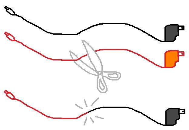
 
Seraph830 said:
So my final product should look something like this?
Sounds great Seraph. I look forward to seeing your results because I would like to build a sensor bar with the LEDs further apart because stupid Rayman doesn't let you move more than 10 feet or whatever from the screen.

I am no electronics whiz but your diagram looks good. Rather than ground and volts you are dealing with positive and negative because it is DC rather than AC that is coming out of the adaptor. I only mention that because if it were AC and you touched red and black with you inbetween it would hurt but with DC it won't. But if you touch the + and - wires you'll blow the fuse in the AC adaptor if it's plugged in. Sorry for that useless info. :lol
 
Some stuff came up and I wasnt able to get very far at all on this little project of mine. Now that I have more time on my hands I'm ready to get back into it. I just ordered 20 LED's and they should be here in 4 days.

I dug around for what AC Adapters I had lying around the house and this is what I found.

Code:
Manufacturer | Original Purpose | Output
----------------------------------------
SEGA           Game Gear          10V DC 0.85A
Thomson        Speakers           12V DC 200mA
Nintendo       NES                 9V AC 1.3A
HON-KWANG      No Clue            12V DC 500mA
Recoton        No Clue            12V DC 150mA
Samsung        Cell Phone          5V DC 0.7A

What would be the best one for me to use? 12V's isnt going to fry anything as long as I use resistors on each LED right? is there a difference between A and mA when talking Currents?

Unfortunatly all these AC adapters I found do not have long enough cords for what I need. Will it be ok to cut up whatever AC adapter cord I want to use and "extend" it with another AC adapters cord? As in do something like this:
CuttingWire.jpg

Ive done it with speaker wire before, just never something that plugs straight into the wall.

The LED's I bought have a voltage of 1.5V~1.6V and a Current of 60mA, Peak: 120mA. I want to place at least 3 of them on each side angled like the offical sensor bar /|\, so that I dont have to be standing directly in front of the screen.

Also does anyone have any suggestions as to what I can house the two LED custers in when im all done? I am fresh out of ideas and would like something that looks nice. Something plastic would be ideal, as I really do not want to use wood or just leave the LED's bare.

I'm sorry for all these noob questions, or if it seems like I'm trying to get somebody to do the calculating work for me. I am just very ignorant about this and am my questions are genuine.
 
I would use the game gear or hon-kwang adapter. (If you plan on connecting them in parallel)

DO NOT use the NES one.
 
Why limit yourself to only two diodes per point? Use four or more and put a small tinfoil reflector behind them to really boost the light.

Don't attach the diode points too firmly on the wall until you've made sure they are the optimal distance from each other.

Why not on the floor? Is there something in the way? Normally the under screen position is strongly preferred...

Also make sure there isn't any reflective surfaces between you and the diodes (surfaces that are ~ parallel to the line of sight between you and the diodes being the main concern).
 
Squeak said:
Why limit yourself to only two diodes per point? Use four or more and put a small tinfoil reflector behind them to really boost the light.

Don't attach the diode points too firmly on the wall until you've made sure they are the optimal distance from each other.

Why not on the floor? Is there something in the way? Normally the under screen position is strongly preferred...

Also make sure there isn't any reflective surfaces between you and the diodes (surfaces that are ~ parallel to the line of sight between you and the diodes being the main concern).

LEDs have an incredibly narrow cone of visibility, so I doubt reflective backings will do anything.

Then again, I don't remember if he mentioned a specific kind of LED he was using.
 
Mr. Pachunga Chung said:
I would use the game gear or hon-kwang adapter. (If you plan on connecting them in parallel)

DO NOT use the NES one.
Why not the Thomson 12V adapter? I'm worried that if I use 3 LED's for each point at 1.5V a LED it would add up to 9V not giving me much to work with. Or with this kind of thing is it ok to have "just enough" power?

Squeak said:
Why limit yourself to only two diodes per point? Use four or more and put a small tinfoil reflector behind them to really boost the light.
I'm using 3 diodes per point. One pointing forward and two pointing off to the sides. The tinfoil behind them wouldnt do much becuase the LEDs have a 30degree angle of projection.
Squeak said:
Don't attach the diode points too firmly on the wall until you've made sure they are the optimal distance from each other.
yeah, im measuring it beforehand using a distance calculator I made. Plus if they are too far apart I can always coil the wire inbetween them.
Squeak said:
Why not on the floor? Is there something in the way? Normally the under screen position is strongly preferred...
There is nothing in the way, but the projector does not project the screen right to the floor, there is about a 2 foot gap in between. Since I want to get this setup to be as close to pointing at the screen as possible, i want the sensor to be at the edge of the screen. Plus I dont trust the floor, we have animals and well as careless people and I dont want this thing where it might get stepped on, bumped, or vacumed.
 
Seraph830 said:
I'm using 3 diodes per point. One pointing forward and two pointing off to the sides. The tinfoil behind them wouldnt do much becuase the LEDs have a 30degree angle of projection.
The pointing off to the sides thing might be a bad idea as the wiimote will see a varying amount of light depending on where you hold it in the room, that could cause some erratic behaviour. Putting a diffuser, like a sanded piece of plexiglas in front of the diodes would give you a much more even dispersion of light.

About the reflector, yes, diodes project most of their light in a narrow beam but there is also lot going off to the sides, that can be seen with the naked eye with visible light diodes, it might be more for long wavelength light, like IR.
Putting a reflector behind 3 diodes might give you a whole extra diode worth of light.

yeah, im measuring it beforehand using a distance calculator I made. Plus if they are too far apart I can always coil the wire inbetween them.
Don't think that things like this just scale linearly, there's stuff like parallax shift and the cone of vision for the wiimote, that are unknown factors. Probably better to experiment than to blindly trust math to much.

There is nothing in the way, but the projector does not project the screen right to the floor, there is about a 2 foot gap in between. Since I want to get this setup to be as close to pointing at the screen as possible, i want the sensor to be at the edge of the screen.
I'm not saying you should put then directly on the floor, hang them just under the projection area.
Everybody who have tried both under and over screen, feel that the under position feel a lot more like pointing at the screen, plus you don't lose tracking nearly as often. Maybe it has something to do with your hand being naturally inclined to point slightly downwards after some time.

Plus I dont trust the floor, we have animals and well as careless people and I dont want this thing where it might get stepped on, bumped, or vacumed.
Again, don't put them on the floor, hang them on the wall in that 2 foot gab you talked about.
If you have animals that haven't learned to not touch your electronics, you might have bigger problems than a pair of cheap homemade diode boxes on the wall.

Actually if you are up for a challenge I might have an even better idea. A sensorbar projector.
Buy a cheap, possibly broken, still projector. Rip out all the unnecessary insides like the lamp, carousel etc, eccept the optics.
Put a very tiny but very powerful sensorbar where the lamp was before.
Now you have a very flexible sensorbar that you can zoom in and out, unsharpen and move around in the room with very little trouble (put the sensorbar projector next to your image projector).
Having a digital camera so you can see where the light is projected might be an advantage and putting two small pieces of reflective tape on the wall, once you found a sweet spot might also be good.
 
Top Bottom