2. Internal Configuration of Game Device 3
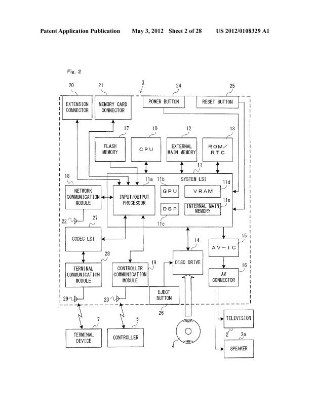
[0122] An internal configuration of the game device 3 will be described with reference to FIG. 2. FIG. 2 is a block diagram illustrating an internal configuration of the game device 3. The game device 3 includes a CPU (Central Processing Unit) 10, a system LSI 11, an external main memory 12, a ROM/RTC 13, a disc drive 14, and an AV-IC 15.
[0123] The CPU 10 performs game processes by executing a game program stored, for example, on the optical disc 4, and functions as a game processor. The CPU 10 is connected to the system LSI 11. The external main memory 12, the ROM/RTC 13, the disc drive 14, and the AV-IC 15, as well as the CPU 10, are connected to the system LSI 11. The system LSI 11 performs processes for controlling data transmission between the respective components connected thereto, generating images to be displayed, acquiring data from an external device(s), and the like. The internal configuration of the system LSI 11 will be described below. The external main memory 12 is of a volatile type and stores a program such as a game program read from the optical disc 4, a game program read from a flash memory 17, and various data. The external main memory 12 is used as a work area and a buffer area for the CPU 10. The ROM/RTC 13 includes a ROM (a so-called boot ROM) incorporating a boot program for the game device 3, and a clock circuit (RTC: Real Time Clock) for counting time. The disc drive 14 reads program data, texture data, and the like from the optical disc 4, and writes the read data into an internal main memory 11e (to be described below) or the external main memory 12.
[0124] The system LSI 11 includes an input/output processor (I/O processor) 11a, a GPU (Graphics Processor Unit) 11b, a DSP (Digital Signal Processor) 11c, a VRAM (Video RAM) 11d, and the internal main memory 11e. Although not shown in the figures, these components 11a to 11e are connected with each other through an internal bus.
[0125] The GPU 11b, acting as a part of a rendering mechanism, generates images in accordance with graphics commands (rendering commands) from the CPU 10. The VRAM 11d stores data (data such as polygon data and texture data) necessary for the GPU 11b to execute the graphics commands. When images are generated, the GPU 11b generates image data using data stored in the VRAM 11d. In the present embodiment, the game device 3 generates both game images displayed on the television 2 and game images displayed on the terminal device 7. Hereinafter, the game images displayed on the television 2 may be referred to as the "television game images", and the game images displayed on the terminal device 7 may be referred to as the "terminal game images".
[0126] The DSP 11c, functioning as an audio processor, generates sound data using sound data and sound waveform (e.g., tone quality) data stored in one or both of the internal main memory 11e and the external main memory 12. In the present embodiment, game sounds are outputted from the speaker of the television 2 and game sounds are outputted from the speaker of the terminal device 7. Hereinafter, the game sounds outputted from the television 2 may be referred to as a "television game sounds", and the game sounds outputted from the terminal device 7 may be referred to as a "terminal game sounds".
[0127] As described above, of the images and sounds generated in the game device 3, data of the images and sounds outputted from the television 2 is read out by the AV-IC 15. The AV-IC 15 outputs the read-out image data to the television 2 via an AV connector 16, and outputs the read-out sound data to the speaker 2a provided in the television 2. Thus, images are displayed on the television 2, and sounds are outputted from the speaker 2a.
[0128] Of the images and sounds generated in the game device 3, data of the images and sounds outputted from the terminal device 7 are transmitted to the terminal device 7 by an input/output processor 11a, etc. The data transmission to the terminal device 7 by the input/output processor 11a, or the like, will be described below.
[0129] The input/output processor 11a exchanges data with components connected thereto, and downloads data from an external device(s). The input/output processor 11a is connected to the flash memory 17, a network communication module 18, a controller communication module 19, an extension connector 20, a memory card connector 21, and a codec LSI 27. An antenna 22 is connected to the network communication module 18. An antenna 23 is connected to the controller communication module 19. The codec LSI 27 is connected to a terminal communication module 28, and an antenna 29 is connected to the terminal communication module 28.
[0130] The game device 3 can be connected to a network such as the Internet to communicate with external information processing devices (e.g., other game devices, various servers, computers, etc.). That is, the input/output processor 11a can be connected to a network such as the Internet via the network communication module 18 and the antenna 22 to communicate with an external information processing device(s) connected to the network. The input/output processor 11a regularly accesses the flash memory 17, and detects the presence or absence of any data which needs to be transmitted to the network, and when detected, transmits the data to the network via the network communication module 18 and the antenna 22. Further, the input/output processor 11a receives data transmitted from an external information processing device and data downloaded from a download server via the network, the antenna 22 and the network communication module 18, and stores the received data in the flash memory 17. The CPU 10 executes a game program so as to read data stored in the flash memory 17 and use the data, as appropriate, in the game program. The flash memory 17 may store game save data (e.g., game result data or unfinished game data) of a game played using the game device 3 in addition to data exchanged between the game device 3 and an external information processing device. The flash memory 17 may also store a game program(s).
[0131] The game device 3 can receive operation data from the controller 5. That is, the input/output processor 11a receives operation data transmitted from the controller 5 via the antenna 23 and the controller communication module 19, and stores (temporarily) it in a buffer area of the internal main memory 11e or the external main memory 12.
[0132] The game device 3 can exchange data such as images and sounds with the terminal device 7. When transmitting game images (terminal game images) to the terminal device 7, the input/output processor 11a outputs data of game images generated by the GPU 11b to the codec LSI 27. The codec LSI 27 performs a predetermined compression process on the image data from the input/output processor 11a. The terminal communication module 28 wirelessly communicates with the terminal device 7. Therefore, image data compressed by the codec LSI 27 is transmitted by the terminal communication module 28 to the terminal device 7 via the antenna 29. In the present embodiment, the image data transmitted from the game device 3 to the terminal device 7 is image data used in a game, and the playability of a game can be adversely influenced if there is a delay in the images displayed in the game. Therefore, it is preferred to eliminate delay as much as possible for the transmission of image data from the game device 3 to the terminal device 7. Therefore, in the present embodiment, the codec LSI 27 compresses image data using a compression technique with high efficiency such as the H.264 standard, for example. Other compression techniques may be used, and image data may be transmitted uncompressed if the communication speed is sufficient. The terminal communication module 28 is, for example, a Wi-Fi certified communication module, and may perform wireless communication at high speed with the terminal device 7 using a MIMO (Multiple Input Multiple Output) technique employed in the IEEE 802.11n standard, for example, or may use other communication schemes.
[0133] The game device 3 transmits sound data to the terminal device 7, in addition to image data. That is, the input/output processor 11a outputs sound data generated by the DSP 11c to the terminal communication module 28 via the codec LSI 27. The codec LSI 27 performs a compression process on sound data, as with image data. While the compression scheme for sound data may be any scheme, it is preferably a scheme with a high compression ratio and little sound deterioration. In other embodiments, the sound data may be transmitted uncompressed. The terminal communication module 28 transmits the compressed image data and sound data to the terminal device 7 via the antenna 29.
[0134] Moreover, the game device 3 transmits various control data to the terminal device 7 as necessary, in addition to the image data and the sound data. Control data is data representing control instructions for components of the terminal device 7, and represents, for example, an instruction for controlling the lighting of a marker section (a marker section 55 shown in FIG. 10), an instruction for controlling the image-capturing operation of a camera (a camera 56 shown in FIG. 10), etc. The input/output processor 11a transmits control data to the terminal device 7 in response to an instruction of the CPU 10. While the codec LSI 27 does not perform a data compression process in the present embodiment for the control data, it may perform a compression process in other embodiments. The above-described data transmitted from the game device 3 to the terminal device 7 may be encrypted as necessary or may not be encrypted.
[0135] The game device 3 can receive various data from the terminal device 7. In the present embodiment, the terminal device 7 transmits operation data, image data and sound data, the details of which will be described below. Data transmitted from the terminal device 7 are received by the terminal communication module 28 via the antenna 29. The image data and the sound data from the terminal device 7 are subjected to a compression process similar to that on the image data and the sound data from the game device 3 to the terminal device 7. Therefore, these image data and sound data are sent from the terminal communication module 28 to the codec LSI 27, and subjected to an expansion process by the codec LSI 27 to be outputted to the input/output processor 11a. On the other hand, the operation data from the terminal device 7 may not be subjected to a compression process since the amount of data is small as compared with images and sounds. It may be encrypted as necessary, or it may not be encrypted. After being received by the terminal communication module 28, the operation data is outputted to the input/output processor 11a via the codec LSI 27. The input/output processor 11a stores (temporarily) data received from the terminal device 7 in a buffer area of the internal main memory 11e or the external main memory 12.
[0136] The game device 3 can be connected to another device or an external storage medium. That is, the input/output processor 11a is connected to the extension connector 20 and the memory card connector 21. The extension connector 20 is a connector for an interface, such as a USB or SCSI interface. The extension connector 20 can receive a medium such as an external storage medium, a peripheral device such as another controller, or a wired communication connector which enables communication with a network in place of the network communication module 18. The memory card connector 21 is a connector for connecting thereto an external storage medium such as a memory card (which may be of a proprietary or standard format, such as SD, miniSD, microSD, Compact Flash, etc.). For example, the input/output processor 11a can access an external storage medium via the extension connector 20 or the memory card connector 21 to store data in the external storage medium or read data from the external storage medium.
[0137] The game device 3 includes a power button 24, a reset button 25, and an eject button 26. The power button 24 and the reset button 25 are connected to the system. LSI 11. When the power button 24 is on, power is supplied to the components of the game device 3 from an external power supply through an AC adaptor (not shown). When the reset button 25 is pressed, the system LSI 11 reboots a boot program of the game device 3. The eject button 26 is connected to the disc drive 14. When the eject button 26 is pressed, the optical disc 4 is ejected from the disc drive 14.
[0138] In other embodiments, some of the components of the game device 3 may be provided as extension devices separate from the game device 3. In this case, an extension device may be connected to the game device 3 via the extension connector 20, for example. Specifically, an extension device may include components of the codec LSI 27, the terminal communication module 28 and the antenna 29, for example, and can be attached/detached to/from the extension connector 20. Thus, by connecting the extension device to a game device which does not include the above components, the game device can communicate with the terminal device 7.

")
