*update*
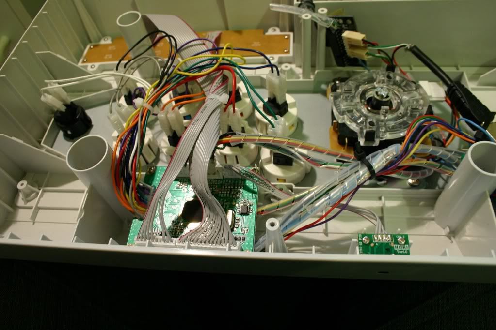
So as i posted before the 360 had a bad PCB, it works fine on computer but not on 360. I tried even replacing the security chip, no dice. So I decided to gut it and put another 360 PCB in there (from my previous stick) but there was still the issue of the panel. So to go around that I basically "routed" the LEDs from the controller to the one on the panel. Kind of tricky to explain, but it's the same general concept used to padhack (you are essentially swapping one part of the circuit for another).

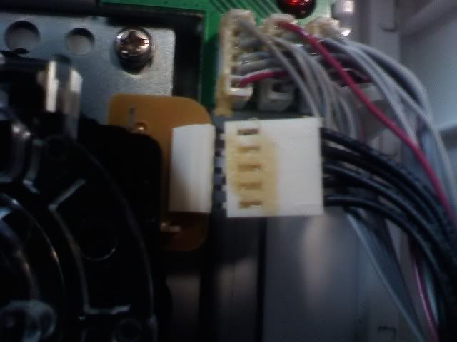
Pictured above is the top panel, To avoid excessive wiring I removed the Zener diode (originally for the +5V input), made the resulting pinout for the guide button, and each LED has it's own pinout already, just attach the pins to the (removed) led pins on the main PCB. The yellow wire is just due to me ripping the trace by accident

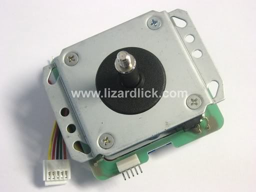
That's the main PCB with the LEDs removed. The lower solder points all go to their own individual resistor, the upper solder points are all connected (and then connected to some power source, dunno if it's directly to +5v VCC or not)
So with that all done it works almost like the original 360 SE, only thing i'm missing is turbo functionality and the LS/DP/RS switch actually doing something.


Can barely tell . Just kind of irritated that i had to put a 360 PCB in a 360 Stick for it to function properly.
Next on the list is to change the USB port. don't like having cords sticking out.
And I will probably make the turbo LEDs activate on button press if i have the time.
So as i posted before the 360 had a bad PCB, it works fine on computer but not on 360. I tried even replacing the security chip, no dice. So I decided to gut it and put another 360 PCB in there (from my previous stick) but there was still the issue of the panel. So to go around that I basically "routed" the LEDs from the controller to the one on the panel. Kind of tricky to explain, but it's the same general concept used to padhack (you are essentially swapping one part of the circuit for another).

Pictured above is the top panel, To avoid excessive wiring I removed the Zener diode (originally for the +5V input), made the resulting pinout for the guide button, and each LED has it's own pinout already, just attach the pins to the (removed) led pins on the main PCB. The yellow wire is just due to me ripping the trace by accident

That's the main PCB with the LEDs removed. The lower solder points all go to their own individual resistor, the upper solder points are all connected (and then connected to some power source, dunno if it's directly to +5v VCC or not)
So with that all done it works almost like the original 360 SE, only thing i'm missing is turbo functionality and the LS/DP/RS switch actually doing something.


Can barely tell
. Just kind of irritated that i had to put a 360 PCB in a 360 Stick for it to function properly. Next on the list is to change the USB port. don't like having cords sticking out.
And I will probably make the turbo LEDs activate on button press if i have the time.


")